Decoderizer
Accessory Bus Circuit Protection Board - ACP101-X1 200 mA
Accessory Bus Circuit Protection Board - ACP101-X1 200 mA
58 en existencias
No se pudo cargar la disponibilidad de retiro
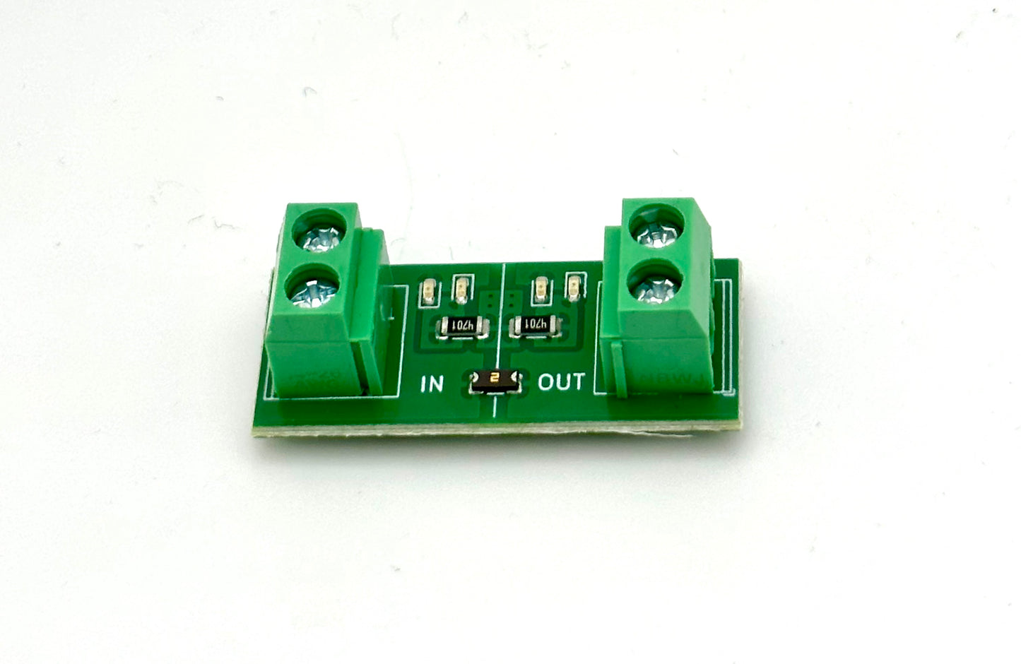
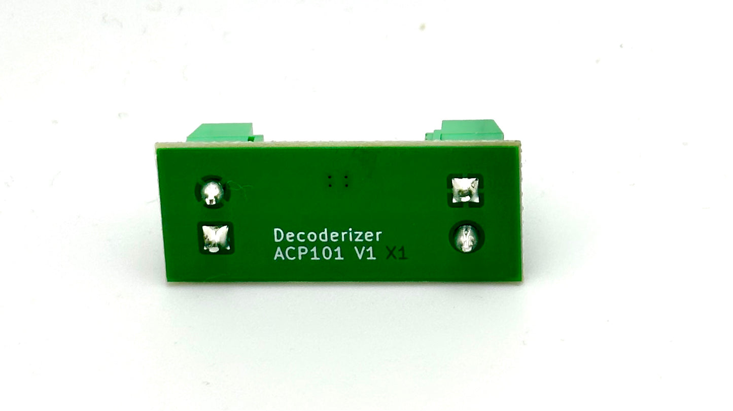
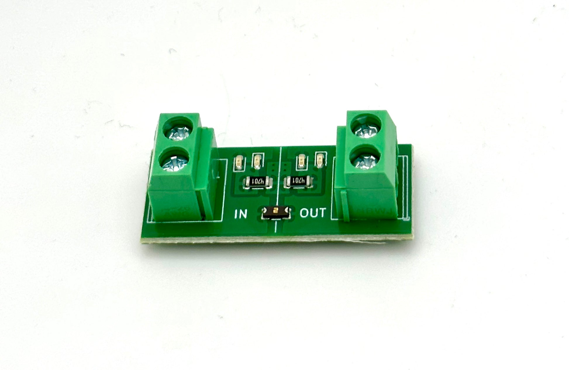
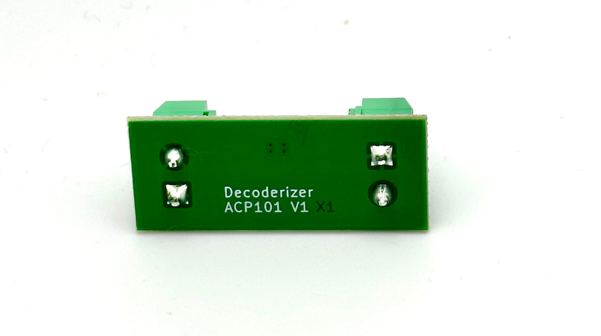
The Accessory Bus Circuit Protection board provides short circuit protection to accessory electronics powered by the Accessory Bus on model railroad modules such as Free-moN and Free-mo. The board includes a PTC resettable fuse element, along with LEDs on both the input and output side of the fuse.
The LEDs indicate the status of the PTC fuse element at a glance: LEDs lit on both the input and output sides of the board indicate that the fuse is conducting, while LEDs lit only on the input side indicate that the fuse is tripped. One LED lit on a side indicates that the power applied is DC. Two LEDs lit on a side indicates that the power applied is either AC or DCC.
Hold current for the PTC fuse element is 200 milliamps. Current drawn in excess of the hold current will result in the fuse element tripping. Time to trip depends on the amount of current drawn, at 1.0 Amp time to trip is 0.6 seconds.
Maximum input voltage is 24 Volts DC or DCC, and 18 Volts AC. Maximum current is 10 Amps. Do not operate the Accessory Bus Circuit Protection board beyond the maximum input voltage and current ratings, as this could result in damage to the PTC resettable fuse element or indicator LEDs, and possibly lead to electrical arcing and/or fire.
The Accessory Bus Circuit Protection board is intended to protect against adverse effects of temporary over-current or over-temperature conditions up to rated limits, and is not intended to serve as a protective device where over-current or over-voltage conditions are expected to be repetitive or prolonged.
Share


